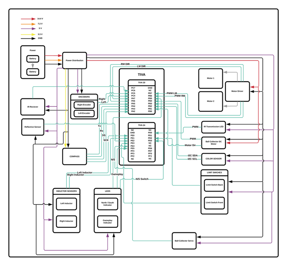
Main System Block Diagram
This shows all of the power, ground, and signal I/O of the entire system.
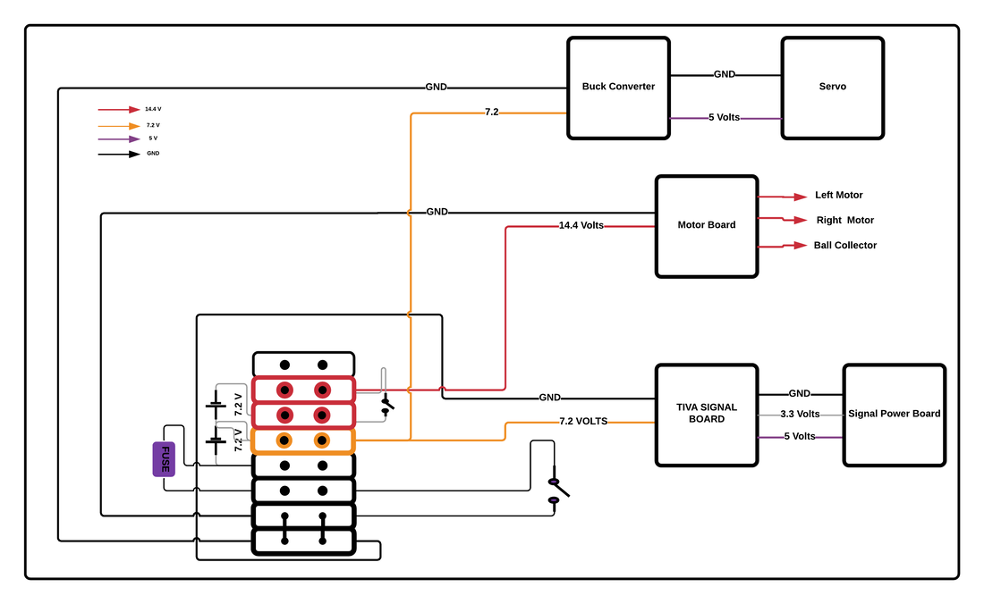
Power Distribution
The power distribution incorporated a terminal block that would house the common ground for the system, a switch to control power to the robot, a fuse that would protect the robot from high current spikes, two 7.2V batteries in series, a second switch to control power to the motors, and power cables for the DC motors, the servo and high current LEDs, and the TIVA protection board.
The TIVA was powered off of 7.2 Volts, which was regulated down to 5 and 3.3V from the TIVA protection board. The power from the TIVA was used to power all sensor and low current circuits on the robot that operated at 5 or 3.3 V.
A buck regulator was used to step down the 7.2 volts from the first battery to 5V to power the servo and high current LEDs. These were powered in this way to allow high current draw that would not affect the voltage going to the other 5V circuits.
Finally, the DC motors were powered off of 14.4 V. This high voltage line powered a motor board that was used to control each motor.
Main System Control
A single TIVA board was used to control all input/output for all the circuits on the robot.
A COMPASS was used to communicate with the main game board. This would tell the board which team the robot was at the beginning of the game. Throughout the gameplay this COMPASS would query the state of the game, team scores, the color of recyclable balls, and which recycle center to use.
A color sensor communicated with the TIVA using I2C. This was used to determine the color of the collected balls and sort into trash or recycling.
|
|
|
Motor Drive
We used two DC motors to move the robot with each one controlled by a TLE-5208 Motor Driver.
The encoders were used to measure and set the speed of the motors, and measure and set the distance the robot travels. This was crucial to our robot as it allowed us to use dead reckoning to go to the catching point even in the event of unexpected collisions, allowed us to implement the line following control algorithm, and aided us in detecting collisions while turning.
The encoders were used to measure and set the speed of the motors, and measure and set the distance the robot travels. This was crucial to our robot as it allowed us to use dead reckoning to go to the catching point even in the event of unexpected collisions, allowed us to implement the line following control algorithm, and aided us in detecting collisions while turning.
Trackwire Inductor Circuit
Our game strategy focused around being able to easily and repeatably navigate to our designated recycling center. To do this we implemented line following control to be able to follow the line connecting the two recycling centers. In order to achieve this we could have used tape sensors to follow the black tape or an inductive sensor to track the current carrying wire. We chose the latter because tape sensing is not the most robust sensing and can give faulty readings depending on the strength of ambient light.
The track wire circuit used an indicator in a LRC circuit to generate a sinusoidal voltage proportional to the strength of the magnetic field generated by the current-carrying wire. In the LC circuit we used an 8.2 mH inductor in parallel with .01uF and .047uF capacitors to generate a resonant frequency equal to the 20kHz AC current in the wire. The 10K resistor was added in parallel to reduce the infinite peak voltage. The ground of this circuit was centered around 2.5V as the Op-Amps were powered between 0-5 volts. The signal from this LRC circuit was passed through a buffer to isolate current draw, a high pass filter to attenuate any DC noise, a gain stage to increase the peak-peak voltage signal, and finally a low-pass filter to attenuate any very high AC noise.
Once a clean sinusoidal voltage was achieved, the signal was converted to analog using a peak detection circuit. This peak detection circuit would hold the last peak voltage of the signal and would drain due to the RC circuit connected to it. This signal was passed through another buffer before being read through an analog input on the TIVA.
Two of these circuits were built and each inductor was placed on the bottom of the robot on opposing sides of the center of the robot. A proportional control law was implemented to measure the difference in voltage readings from these inductors and control the wheel speeds to maintain the robot directly over the line. This method worked very well and allowed our robot to consistently drive to the recycling centers to deposit balls.
Ball Collector Mechanisms
We implemented a simple, yet robust design to collect balls. A single DC motor would spin a collector wheel that would scoop up balls from the field. Once collected, the color sensor would sort the balls. If the collected ball was determined to be TRASH, the trapdoor servo would open and discard the ball back onto the field. If the ball was RECYCLE, the collector wheel would continue spinning, keeping the ball in place. To dispense the balls, we would reverse the direction of the DC motor to shoot the balls back out.
Beacon Detection
A photo-transitive circuit was used to detect the frequency of pulses from the recycle and trash centers. A phototransistor, upon excitement via IR light, would create a current that would pass through a resistor to create an oscillating voltage. This signal would then pass through two gain stages to increase the excitement voltage from the photo-transitive circuit. Before each gain stage, the signal was passed through a AC coupling high pass filter to attenuate any DC noise such as ambient light. Finally, the signal was passed through a comparator with hysteresis to convert the signal into a digital signal. This would then be fed into the TIVA.
A virtual ground of 2.5 V was used to center the signal voltage as the Op-Amps operated between 0 - 5 volts.
A virtual ground of 2.5 V was used to center the signal voltage as the Op-Amps operated between 0 - 5 volts.
Recycling Center IR Transmitter |
Bumpers |
|
To communicate with the recycling centers, an IR transmitter circuit was used. Three IR LEDs in parallel were used to blast the centers to open them. An N-channel MOSFET was used to modulate the frequency at which the LEDs pulsed.
|
Limit switches on the front and back of the robot were used to detect any collisions.
|
|
|
|
Game Indicator LEDS
To indicate the status of the game, we would use a single green LED that would be on during gameplay, and off during all other times.
Two different sets of LEDs were used to indicate whether the robot was the North or South team. We used a simple Schmitt trigger inverter (74HCT14) to toggle between north/south and a power MOSFET (IRLZ34N) as a switch for the dazzling bright LEDs (check gallery).
A simple HI/LO indication using a switch was used to designate whether the robot should register as the north team or the south team.
|
|
|
